This research into Galvanic Skin Response detection was done for the ITP Class “Computers for the Rest of You”. Many people have found this information useful so I’m posting it here.
Super Simple GSR Circuit:
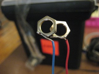
The electrodes are made from 2 hex nuts from the pcomp lab. I had to sand one side to hold the solder. Press the hex nuts against two fingers and you should see the values change.
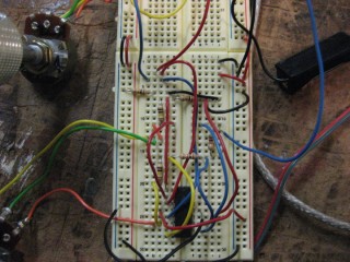
The breadboard is a simple variable resistor. It takes 5v from the arduino board and sends it to the red electrode. The blue electrode is the “Sensor” and uses a 200k (actually 2 100k) resistor to create the appropriate pulldown. This can be varied to give more or less sensitivity.
The breadboard is connected to analog input 0
A More Sophisticated GSR Circuit:
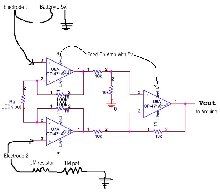
You will need 3 Op Amps. Mine uses a chip from Radio Shack that has 4 Op Amps(LM324N). I built this diagram so that “Rf” = 100k resistors and “Rg” = a 100k pot. “Vin1” and “Vin2” are fed by the finger electrodes. One electrode gets 1.5v (from an external battery) and the other electrode has a 1M resistor and a 1M pot going into ground. Power the op Amps with the 5V Arduino power and make sure that the arduino and the battery share ground.
This is modified from this pdf.
The Code below should work with this circuit.
LINKS:
The Maker Store now has a complete GSR Kit! There’s also circuit diagrams and instructions.
Similar project from Cornell.
emotion mapping project from the Royal College of Art, England
Instrumental Amplifier Schematic and general info on Op Amps


